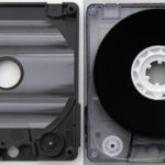
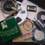
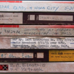
- Why Cassette Tapes Won’t Play
 Learn why old cassette tapes jam, break, sound dull, or stop playing entirely. Well-known audio restoration engineer Mike Konopka explains the most common cassette failures and how damaged tapes can often still be restored.
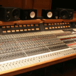
 - Five Ways To Improve Listening In Your Control RoomFive Ways To Improve Listening In Your Control Room Control rooms? Hah! In today’s digital music production world control rooms are now situated in dining rooms, bedrooms, basements, attics and placed almost anywhere. Anywhere that is except in the dwindling number of actual professional recording studios clinging still to life! Back in the day, the… Read more: Five Ways To Improve Listening In Your Control Room
- Bound Unto Root-In Good Faith: An Analog Audio JourneyBound Unto Root-In Good Faith: An Analog Audio Journey a guest blog by Dominic Francisco, a mikekonopka.com client As a little kid, I would often get lost in imagination. This was especially prevalent duringbath time, when my mom would entertain me with cassettes featuring fables for children. They were jubilant little moral fantasies that captivated… Read more: Bound Unto Root-In Good Faith: An Analog Audio Journey
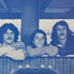
- The Freeze Band-A Restoration StoryThe Freeze Band-A Restoration Story a guest blog by Andrew Luxem, a mikekonopka.com client This year, 2022 marks a major milestone for my dad (he’s turning the big 7-0!) and I wanted to do something special for him. In the 1970s and 1980s, my dad played in a band called The Freeze Band. He played… Read more: The Freeze Band-A Restoration Story
- tape-restoration.com FAQs Simplify Audio Restorationstape-restoration.com FAQs Simplify Audio Restorations Audio expert Mike Konopka and tape-restoration.com have distilled the many questions their wonderful audio restoration clients have asked over the years into one simple FAQ page. There you’ll find all the answers you’re looking for in high quality restorations of your important audio. Are you looking for answers about your… Read more: tape-restoration.com FAQs Simplify Audio Restorations
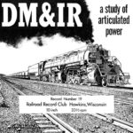
- Audio Restoration Leads To New Book!Audio Restoration Leads To New Book! Now Available – A Guide to the Railroad Record Club E-Book tape-restoration.com/mikekonopka.com client Kenneth Gear has written and compiled a complete history of William Steventon‘s Railroad Record Club, which issued 42 different LPs of steam, electric, and diesel railroad audio, beginning with its origins in 1953. Author Kenneth Gear… Read more: Audio Restoration Leads To New Book!
- Hear The Music Of Sari & KayThe Music of Sari & Kay Sari & Kay are the Chicago musical duo of Sari Greenberg and Mike Konopka who have been creating music tracks together since the summer of 2018. They are adept songwriters and producers in the realms of Rock, Country, R&B, Blues, Ambient, and Dance music styles. Sari & Kay first… Read more: Hear The Music Of Sari & Kay
- Audio Restoration-The Railroad Record ClubAudio Restoration-The Railroad Record Club Audio Restoration-The Railroad Record Club. For many years, in addition to my audio engineering, production and acoustical consulting, I’ve enjoyed restoring analog audio for a vast array of unique people. Projects can be as simple as restoring a cassette of a long departed family member’s voice to projects as complex… Read more: Audio Restoration-The Railroad Record Club
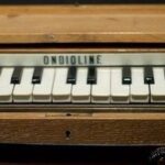
- Peter Glushanok Early Electronic Music ComposerPeter Glushanok Early Electronic Music Composer Adventures in Audio Restoration For many years, in addition to my audio engineering, production and acoustical consulting, I’ve enjoyed restoring analog audio for a vast array of unique people. Projects can be as simple as restoring a cassette of a long departed family member’s voice discovered in the bottom… Read more: Peter Glushanok Early Electronic Music Composer
- Bobby Graham UK’s Greatest DrummerBobby Graham UK’s Greatest Drummer © Mike Konopka While working for Ray Davies, I had the opportunity to record one of the world’s greatest drummers. It was during 1997 in North London at the Kinks’ Konk Studios. His name was Bobby Graham and he played on an astounding 15000 songs, including “We Gotta Get Out… Read more: Bobby Graham UK’s Greatest Drummer
- Meeting Leo Fender & The Chicago NAMM ShowsMeeting Leo Fender & The Chicago NAMM Shows © Mike Konopka I am a lucky guitar player because I met Leo Fender. It was in Chicago at the summer NAMM show in 1982. Leo reminded me of my Dad. Back in ’82 I was a struggling guitar player teaching lessons in this crazy music store… Read more: Meeting Leo Fender & The Chicago NAMM Shows
- Recording Better Vocal TakesRecording Better Vocal Takes © Mike Konopka Recording quality vocal performances is perhaps the most important aspect in the success of your music projects. Here’s several tips to help you capture great vocals: Before recording gain the vocalist’s trust and respect: As an audio pro, or even just the person in charge of recording, it’s… Read more: Recording Better Vocal Takes
- Six Ways To Keep Vacuum Tube Gear HappySix Ways To Keep Vacuum Tube Gear Happy Want to keep your tube guitar amps maintained and other tube gear tuned up & operating ? Follow these 6 steps below. My endearment to the vacuum tube began in 1969 when I plugged in my ’66 Gibson SG Special into a newly acquired Silvertone model #1484… Read more: Six Ways To Keep Vacuum Tube Gear Happy
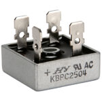
- Basic Power Supply Theory And RepairBasic Power Supply Theory And Repair Do you have an electronic tool kit? Are you skilled with a soldering iron? Can you operate a multimeter? And are you interested in learning more about Basic Power Supply Theory And Repair? Then read on! Now that you have all the aforementioned stuff, you’re probably anxious to tear… Read more: Basic Power Supply Theory And Repair
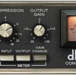
- Secrets Of Audio Side-Chain UseSecrets Of Audio Side-Chain Use Here’s information all about audio side-chains & key-inputs on compression, gating, & dynamics processors. Learn how and why to use them. Have you ever looked sideways in wonderment at the “side-chain input” or “key in” jacks on your compressor/limiters, noise gates, or software plug-ins? What’s an audio side-chain anyway?… Read more: Secrets Of Audio Side-Chain Use
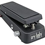
- The Jet-Age Backwards Wah Wah EffectThe Jet-Age Backwards Wah Wah Effect A new trick for your old Wah Wah. Hook it up backwards! Next time your guitar player whips out his Cry Baby wah pedal for a late-nite overdub, take a moment to show him this truly bizarre technique. Here’s how you do it: First, flip the connections on the… Read more: The Jet-Age Backwards Wah Wah Effect
- Hey Is This Thing On?Testing.. testing… hey is this thing on? Welcome to The Ttone Audio Blog!
- w.e.bartolotta tunes from the tale Wonderw.e.bartolotta tunes from the tale Wonder W.E. Bartolotta recently recorded fifteen songs at Mike Konopka’s Pie In the Sky studio for Bartolotta’s unique musical production entitled Wonder. Mike co-produced the music recordings with the author and also played guitar, bass, and sang backing vocals. Nic Barnum supplied additional guitar artistry along with backing vocals. Trish… Read more: w.e.bartolotta tunes from the tale Wonder